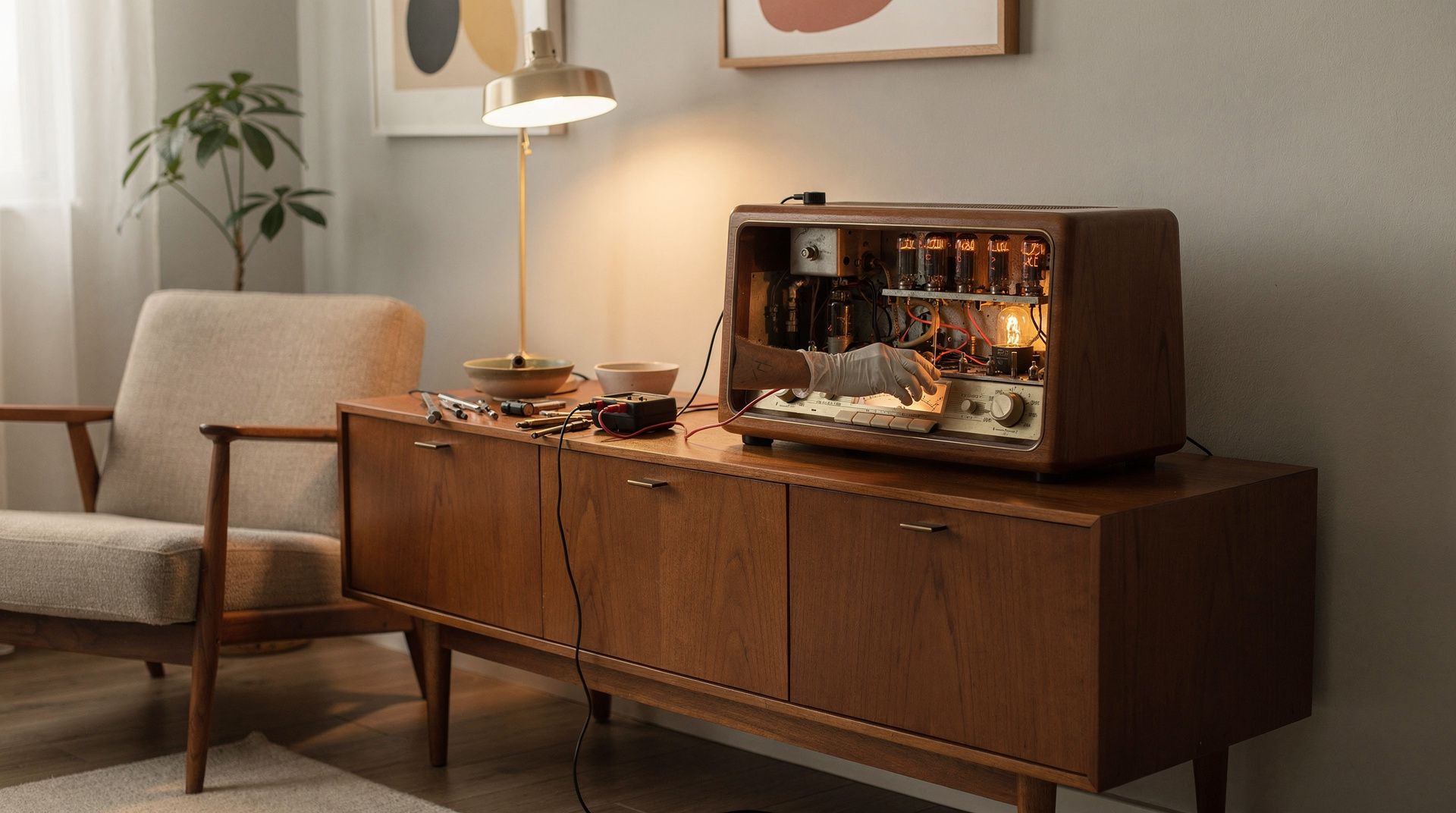
Safely commissioning a tube radio
A tube radio from the 1940s to the 1960s is more than a functioning object. It is a testament to an era in which radio reception had the character of furniture, in which cabinets were crafted from solid timber and chassis wired by hand. Anyone who switches such a device on for the first time after decades in a cellar, an attic or a collection bears responsibility: for their own safety, for the original fabric and for the service life of components that are no longer trivial to replace today.
The three greatest risks have remained the same for decades: moisture-saturated paper and electrolytic capacitors that can fail catastrophically under full load at first switch-on; dangerously touchable anode voltages of typically 200 to 400 volts DC that remain stored in filter capacitors even after switch-off; and transformerless all-mains sets whose chassis may carry mains potential. A calm, methodical initial commissioning via a variable isolation transformer, combined with careful drying and a thorough high-voltage test, is therefore not a luxury for purists but basic technical hygiene. The following sections organise the practice around the materials involved, regional construction traditions and the questions that arise for collectors regarding authenticity and condition.
Characteristic materials and their ageing
The cabinet is the visible part, but not the critical one. Veneered walnut, rosewood or birch bodies, fabric grilles in rayon or jute, and dial glasses in celluloid or early acrylic age with dignity and can be stabilised by conservation methods. What matters for commissioning is what sits beneath the chassis.
Paper capacitors – often wound in waxed card sleeves or the characteristic colourful “sweet” tubes – are regularly moisture-saturated after six to eight decades. They carry leakage currents in the milliamp range and pull the output valve’s grid bias towards zero, thermally destroying the output valve and taking the output transformer with it. Electrolytic capacitors in the power supply lose their forming layer over the years. If they are suddenly subjected to full operating voltage they can break down, build up excess pressure and, in the worst case, vent their electrolyte.
Drying – more precisely: reforming – is carried out via a variable isolation transformer. The mains voltage is raised slowly over several hours from around 30 volts up to the rated voltage, ideally with the valves removed so that only the power supply is loaded. The primary current is monitored throughout. If it falls at constant voltage, the capacitor is reforming. If it remains high or rises, the capacitor must be replaced. With carbon-composition resistors, value drift of 20 percent or more upward must also be expected, especially in hot zones around the output valves.
Regional schools and their construction logic
The German school, shaped by manufacturers such as Grundig, Saba, Telefunken, Nordmende and Loewe, relied almost exclusively in the post-war period on all-mains or AC chassis with a clearly separated mains transformer, often with FM oscillator or ratio detectors and EL84 or EL95 output stages. These sets are electrically predictable; service documentation at Lange, Beier or in the Funkschau archive is comprehensively recorded, and replacement valves from the E-series are available.
The American school – Zenith, Philco, RCA, or the compact Catalin-cased sets from Fada and Emerson – works predominantly with AA5 all-mains circuits without mains isolation. Here an isolation transformer is not an option but a requirement the moment the chassis is accessible for measurement or repair. The 50-series valves (35W4, 50C5, 12BA6) are robust, but the heater circuits are wired in series, which complicates fault-finding when one valve is dead.
The Italian and French post-war modern movement – think Brionvega with Zanuso and the Castiglionis, or Teppaz – combined standard technical chassis with sculptural cabinets. The RR126, for example, is a conventional transistor radio of furniture quality; the TS502 a folding object. With these pieces the circuit complexity is usually modest, but the iconic value of the cabinet justifies an especially gentle restoration with no visible intervention.
Authenticity and condition for collectors
A tube radio has two conditions that must be assessed independently: the conservation condition of the cabinet and the technical condition of the chassis. Both must be disclosed at the point of sale.
For authenticity, what counts first are the original valves with manufacturer-compliant codes, the original loudspeaker with an intact paper cone and free voice coil, the undamaged dial lettering, and the original mains switch and original knobs in Bakelite or Galalith. Reprinted dials, resin-turned replica knobs and modern film capacitors in visible areas reduce the collector value, even if they are technically correct. High-quality restorations replace electrolytic and defective paper capacitors but retain the original capacitor cans as dummies and work underneath the chassis so that the visual appearance of the chassis remains unchanged.
Documentation is decisive. A service record with a logged reforming procedure, a list of replaced capacitors, measured anode voltages and photographic documentation before and after the work clearly distinguishes a set from a mere attic find. Without this documentation, every switch-on is a blind leap that may, in the worst case, ruin a historically valuable piece.
All vintage audio and broadcast objects on mid-centurydesigns.com are electrically tested before being added to stock, reformed professionally where necessary, and delivered with a condition report. You receive transparent information about replaced components, measured operating voltages and the preservation of the original fabric, so that the piece in your home not only stands there but can be played responsibly.
This article was generated automatically by an AI system. Disclosure pursuant to Article 50 of the EU AI Act.